
Downloads
Download


This work is licensed under a Creative Commons Attribution 4.0 International License.
Article
Research on Electrical Boost Technology for Medium-Duty Diesel Engines
Yong Yin *, Jiao Mi, Yanting Zhao, and Zihao Liu
Dongfeng Commercial Vehicle Technical Center, Wuhan 430056, China
* Correspondence: yinyong@dfcv.com.cn
Received: 28 August 2024; Revised: 15 December 2024; Accepted: 25 April 2025; Published: 30 April 2025
Abstract: To meet the increasingly stringent fuel consumption standards and reach the internationally advanced carbon emission levels, the electrification of diesel engine accessories is an important technological approach for energy conservation and emission reduction. Compared with the turbocharging system of traditional diesel engines, the electric boosting system can further improve the charging efficiency of diesel engines and enhance the low-speed torque, transient response, etc. Based on the one-dimensional engine performance simulation software, this paper respectively studies the influence of the electric boosting system on the overall performance of a mass-produced medium-sized diesel engine platform and the corresponding hybrid platform. Firstly, the influence of different layout forms of the electrical boost on the engine performance is studied based on the diesel engine platform. The results show that the series layout form is superior to the parallel one. When the electrical boost is arranged in series at the front, the low-speed torque is increased by 13%, the intake air volume is increased by 44%, and the brake specific fuel consumption (BSFC) is improved by 12%. When arranged in series at the rear, the torque is increased by 11%, the intake air volume is increased by 37%, and the BSFC is improved by 11%. However, considering that if the power consumption of the electrical boost’s motor is sourced from the engine, the BSFC will deteriorate. With the expansion of future diesel engine electrification technologies, the motor can use the electric energy generated by brake power recovery and waste heat recovery. Therefore, the effect of applying the electrical boost in the hybrid vehicle platform is studied. The results show that when the hybrid engine can achieve the same power and torque targets, the series-rear layout form is superior to the series-front one. The specific fuel consumption can be optimized by up to 11%. The rear layout requires the addition of an intercooler, which will lead to an increase in cost. In conclusion, the electric boosting system based on the hybrid platform not only has the advantages of fast dynamic response and solving the turbo lag problem, but also can enhance the vehicle’s power performance and fuel economy to a greater extent by optimizing the matching of the turbocharger and the electric boosting system. The electric boosting system based on medium-sized engines has a more promising commercialization prospect.
Keywords:
diesel engine electrification hybrid power electrical boost fuel economy1. Introduction
The increasingly strict environmental protection policies and fuel consumption regulations have put forward higher and higher requirements for commercial vehicles. To reach the internationally advanced carbon emission level by 2025, commercial vehicles require diesel engines to improve fuel economy while reducing particulate matter (PM) and NOx emissions. Therefore, the energy-saving and emission-reduction technologies for diesel engines have been widely discussed. The use of exhaust gas turbocharging technology to improve the intake air density can not only increase the power per liter of diesel engines and reduce fuel consumption, but also effectively improve engine emissions [1].
Existing traditional diesel engines mainly increase the intake air volume of internal combustion engines through turbocharging technology. In a turbocharging system, the atmosphere is pressurized by the compressor of the turbocharger and then enters the engine intercooler. The cooled pressurized gas enters the cylinder for combustion and power generation. The exhaust gas after power generation enters the turbine through the exhaust manifold to expand and do work, driving the compressor to operate at the same time. Finally, it is discharged through the after-treatment system [2]. Common turbochargers mainly include three types: fixed gate turbochargers (FGT), waste gate turbochargers (WGT), and variable geometry turbochargers (VGT). FGT is usually an uncontrollable turbocharger; in a WGT, the opening and closing of the bypass valve are mainly controlled by the compressor pressure. When the pressure is too high, part of the engine exhaust gas needs to be discharged through the bypass valve. In a VGT, the nozzle ring position can change unrestrictedly between open and closed states, enabling the adjustment of the eddy current flow channel outlet area, boost pressure, etc. [3].
The structure of the turbocharger determines that it is impossible to take into account both low-speed and high-speed conditions simultaneously. When using a WGT, the air-fuel ratio can be improved under low-speed conditions. Under high-speed conditions, to avoid overspeeding of the turbocharger and exceeding the maximum combustion pressure of the engine, the bypass valve needs to be opened for venting. The low-speed performance of a VGT is slightly better than that of a WGT, but when selecting a model, a compromise needs to be considered to match both low-speed and high-speed conditions. All turbochargers have problems such as compromised low-speed performance and poor dynamic response [4].
However, exhaust gas turbochargers need to use exhaust energy to overcome their moment of inertia drive, and there is a problem of slow transient response. Electrical boost has the potential to improve the responsiveness of turbochargers and improve diesel engine acceleration smoke, etc. The optimal matching of electrical boost with turbochargers has more advantages, such as improving inflation efficiency and improving low-speed torque [5,6].
The electrical boosting technologies mainly include electric electrical boost (E-boost), electric auxiliary turbochargers (electrical turbo, E-turbo), and electronic compound turbines, etc. The E-boost technology is usually used together with a conventional turbocharger [7,8], and is installed upstream or downstream of the conventional turbocharger. It increases the boost pressure and the engine’s instantaneous response at low engine speeds, virtually eliminating the turbo lag phenomenon [9,10]. At high speeds, the conventional turbocharger should undertake the boosting task as much as possible. At this time, the E-boost realizes the bypass function with the help of its self-adjusting bypass valve. Through integrated electronic devices, appropriate selection of the engine and corresponding matched engine electronic control system, the power performance, economy, and Noise- Vibration-Harshness (NVH) of the engine can achieve a good match [11,12]. Therefore, with the promotion of 48 V automotive circuits in the future and the improvement of battery and motor technology, as well as the progress of engine turbine compounding [13,14], waste heat recovery and other technologies [15], more efficient and cleaner diesel engine electrification technology or hybrid technology with electric supercharging is one of the important technical paths to meet the future demand for energy saving and emission reduction of vehicles [16,17].
In this paper, based on the mass-produced medium-sized diesel engine platform and an existing electric compressor platform, the simulation analysis of the electric boosting system based on the traditional diesel engine was carried out [18], A preliminary study was conducted on the performance impact and product matching of diesel engine electrification [19]. Then, based on the hybrid platform of the medium-sized engine, a technical study on the electrification of the electrical boosting system for typical hybrid operating conditions was carried out, laying a foundation for further system matching of the entire engine, bench tests, and road tests [20–22].
2. Basic Model Calibration
The base engine was calibrated based on a medium-sized diesel engine with a displacement of 5 L. The basic technical parameters of the diesel engine are shown in Table 1.
| Type | Parameter |
|---|---|
| In-Line 4-Cylinder Four-Stroke, Water-Cooled, Air-to-Air Intercooler | |
| Turbocharger | WGT |
| Bore/mm | 110 |
| Stroke/mm | 132 |
| Displacement/L | 5 |
| Compression ratio | 17.3 |
| Ignition sequence | 1-5-3-6-2-4 |
The engine’s overall power output was measured by a dynamometer. The inlet mass flow rate was measured upstream of the compressor. The uncertainties of the measuring instruments are shown in Table 2. An automatic data acquisition and processing system was established in the engine test bench to measure engine steady-state average parameters. The engine operation conditions (speeds, loads) were controlled by a computer, which was connected to the engine electronic control units (ECU).
| Instrument | Measured Quantity | Uncertainty |
|---|---|---|
| Inductive pick-up sensor | Engine speed | ±10 r/min |
| Dynamometer | Engine torque | ±0.1% |
| Sensyflow air mass flow meter | Air mass flow rate | ±1% |
| AVL fuel mass flow meter | Fuel consumption | ±0.12% |
| K-type thermocouple | Temperature | ±0.75% |
| Strain gauge | Pressure | ±0.2% |
Based on the technical parameters of the engine, a model was established through the 1D performance process simulation software of the engine, and the base engine was checked according to the experiment data. The calibration results are shown in Figure 1. The deviation between the calibration result and the experiment result is guaranteed within 5%. The values of the deviation are shown in Table 3.
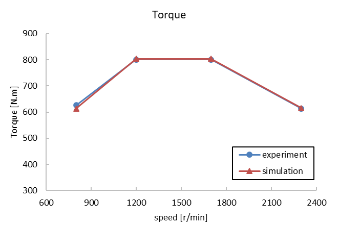
Figure (a). Torque comparison of experiments and simulations
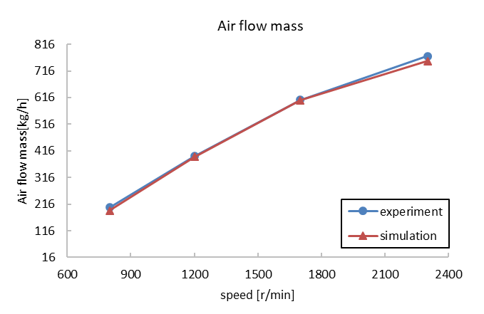
Figure (b). Air flow mass comparison of experiments and simulations
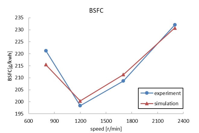
Figure (c). BSFC comparison of experiments and simulations
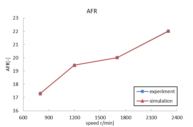
Figure (d). Air Fuel Ratio comparison of experiments and simulations
Figure 1. Calibration results of the model.
| Speed (r/min) | 2300 | 1700 | 1200 | 800 |
|---|---|---|---|---|
| Torque deviation (%) | 0.34 | 0.35 | 0.32 | -2.03 |
| Air mass deviation (%) | -2.50 | -0.26 | -0.64 | -5.00 |
| BSFC deviation (%) | -0.56 | 1.27 | 0.97 | -2.63 |
| AFR deviation (%) | -0.01 | 0.00 | 0.01 | -0.02 |
3. The Electrical Boost
The electrical boost is mainly composed of a compressor and a high-speed motor. Figure 2 shows the sample of the electrical boost used in this research. Electric pressurization technology mainly uses high-speed motors to drive the compressor. The electric compressor has the effect of replenishing air, and the response is fast, so that the engine can be pressurized without lag at low speed. If a bypass valve is connected to the electric supercharger in parallel, the throttle loss in non-supercharging conditions can be avoided [16].
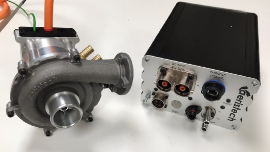
Figure 2. Electrical boost sample.
The arrangement forms of the electrical boosting system are mainly divided into parallel system, front series system, and rear series system, as shown in Figure 3.
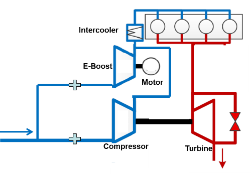
Figure (a). Parallel system
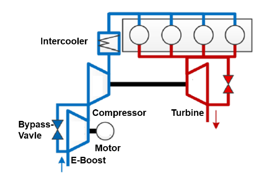
Figure (b). Front series system
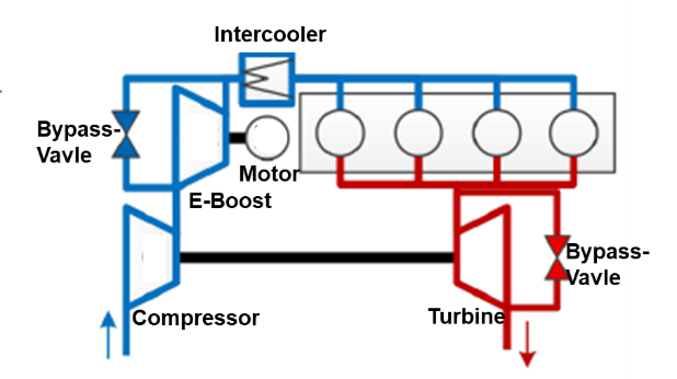
Figure (c). Rear series system
Figure 3. Layout of the electrical boosting system.
4. Research on Parallel E-Boosting System
The one-dimensional performance simulation model of the parallel electrical boosting system is set up, as shown in Figure 4. To explore the potential of power and economy improvement of the engine, the pressure ratio of the turbocharger and the fuel injection and air-fuel ratio of the engine was adjusted, and the increase of maximum power torque, economy and low-speed torque after the parallel arrangement of the electrical boost and the compressor of turbocharger was compared.
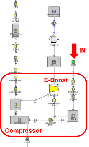
Figure 4. Parallel electrical boosting model.
The simulation results of the parallel electrical boosting system are shown in Figure 5. As can be seen from Figure 5, the parallel arrangement has an effect on power torque, with the maximum low-speed torque increased by 9%, air flow mass improved by 42%, BSFC improved by 9% when motor power consumption was not considered, and BSFC worsened by 10% when motor power consumption was considered.
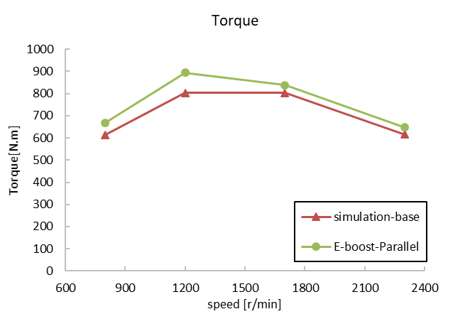
Figure (a). Torque comparison between the parallel type and the base
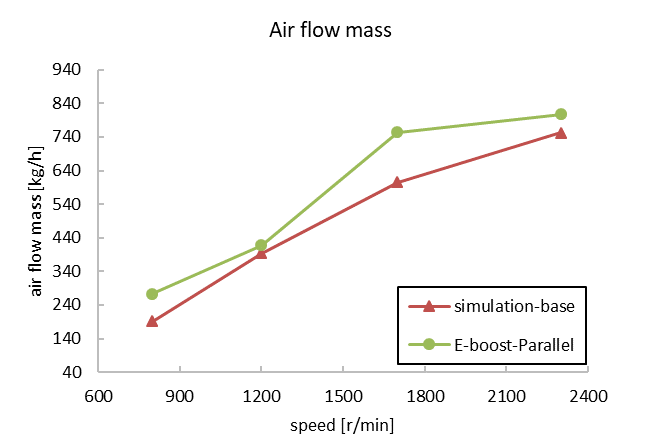
Figure (b). Air flow mass comparison between the parallel type and the base
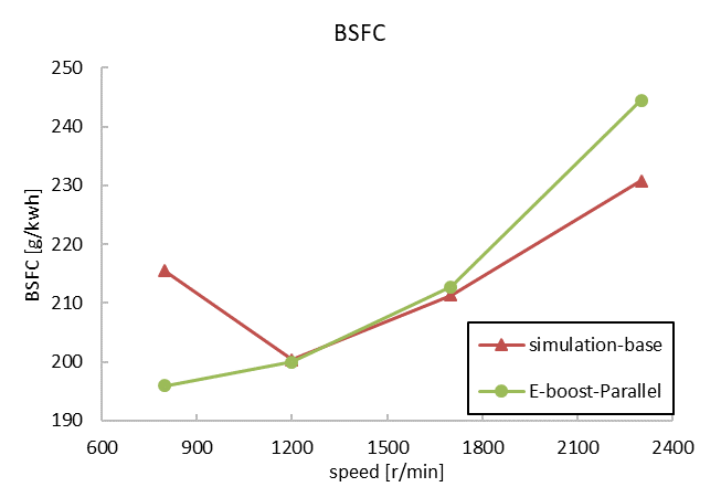
Figure (c). BSFC comparison between the parallel type and the base
Figure 5. Performance of the parallel type.
Considering the expansion of future electrification technology, the motor can use brake power to recover power generation and waste heat to recover power generation, so the power consumption of the motor can be temporarily ignored when evaluating the improvement of fuel consumption of the system.
The map of the pressure end of the electrical boost and turbocharger is shown in Figure 6. Compared with the compressor of the turbocharger, the maximum flow rate of the electrical boost is only 1/2 of the maximum flow rate of the compressor, and the maximum pressure ratio is about 3/4 of the compressor.
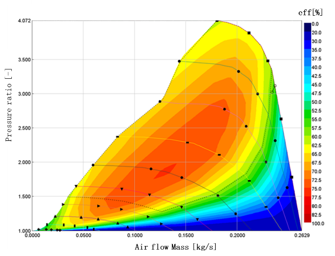
Figure (a). Map of the compressor
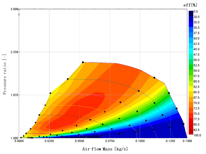
Figure (b). Map of the Electrical boost
Figure 6. Comparison of map between electrical boost and compressor.
Under high-speed conditions, the inlet and outlet pressures of the compressor and the electrical boost in parallel arrangement are the same, but the flow rate and pressure ratio range are quite different, resulting in that when the flow rate and pressure ratio are within the compressor pulse spectrum range, electrical boost will run outside the pulse spectrum range because of the same pressure ratio with the compressor.
At the same time, through the flow judgment of the two pressure ends, it can be seen that under high-speed conditions, electrical boost does not flow through and electrical boost does not work, which is equivalent to the layout structure of the original machine. At this time, the power potential of the parallel layout electrical boosting system is the same as the turbocharger of the original machine and has nothing to do with the electrical boost.
Under low-speed conditions, the electrical boost flow is within the pulse spectrum range, and the pressure ratio exceeds the range. Therefore, it can be attempted to reduce the pressure ratio by adjusting the motor power, as shown in Figure 7. The effect of motor power on torque and specific fuel consumption is: the greater the motor power, the greater the potential to improve torque, and the better the specific fuel consumption. Therefore, even if the motor power is reduced, the parallel arrangement is still too large for the electrical boost pressure ratio, and even if electrical boost can work within the flow range under low-speed conditions, the pressure ratio still does not meet the map requirements.
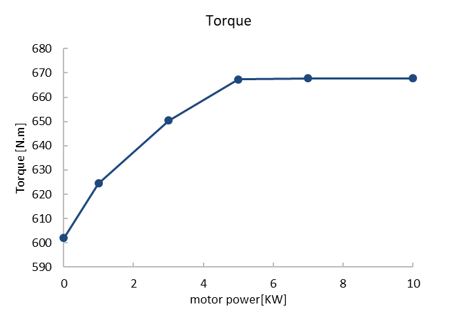
Figure (a). Torque performance at different motor powers
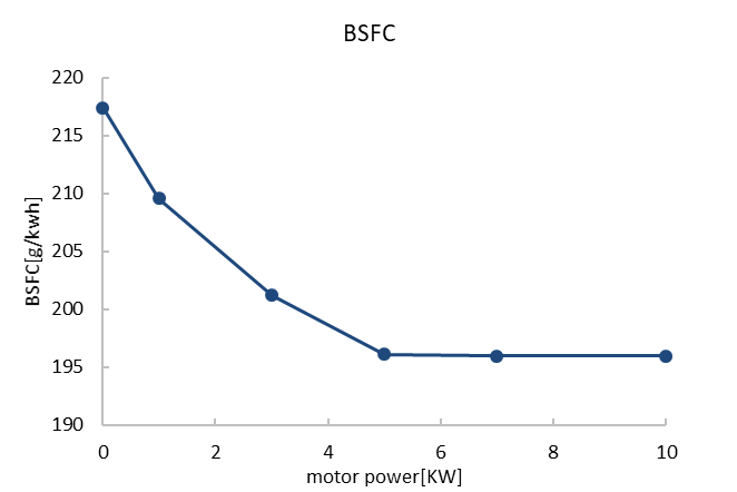
Figure (b). BSFC performance at different motor powers
Figure 7. Performance at different motor powers.
To sum up, in the parallel arrangement, the electrical boost only works at low speed, so the power performance cannot be improved. At low speeds, the electrical boost and the turbocharger need to have the same pressure ratio, but the actual electrical boost has a smaller pressure ratio range than the turbocharger, which will cause the electrical boost not to work. Therefore, although the parallel type is relatively simple, it requires an electrical boost of similar size to the turbocharger, and the two are rematched to achieve the optimal effect.
5. Research on Series E-Boosting System
The one-dimensional performance simulation model of the electrical boosting system is shown in Figure 8. According to the position relationship between the electrical boost and the compressor of the turbocharger, the series electrical boosting system can be divided into two types: front series and rear series. To ensure that the water-cooling temperature of the electrical boost does not exceed the limit value, the intercooler of the electrical boost is added at the rear end of the compressor. In addition, a bypass line with a bypass valve switch is added to ensure the safety of the electrical boost when it is not working. To explore the potential of improving the power performance and economy of the engine, by adjusting the pressure ratio of the turbocharger, adjusting the fuel injection and air-fuel ratio of the engine, and adjusting the switch of the bypass valve, the potential of improving the maximum power torque, economy and low-speed torque of the electrical boost and the compressor of turbocharger of the front and rear series system were compared and analyzed.
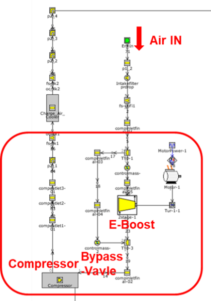
Figure (a). Front series system
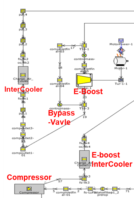
Figure (b). Rear series system
Figure 8. Series electrical boosting model.
The simulation results of the two series electrical boosting systems are shown in Figure 9. The low-speed torque and air flow mass increase by 13% and 44% under the series front. If motor power consumption is not taken into account, BSFC can improve by 12%, while fuel consumption deteriorates by 5% when motor power consumption is taken into account. The series rear lower torque is increased by 11%, the air intake is increased by 37%, the BSFC can be improved by 11% without considering the motor power consumption, and the fuel consumption is worsened by 7%, considering the motor power consumption.
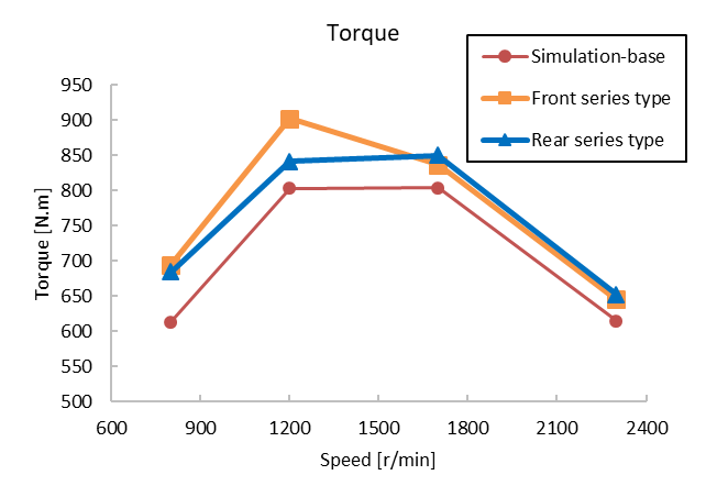
Figure (a). Torque performance between different series types and the base one
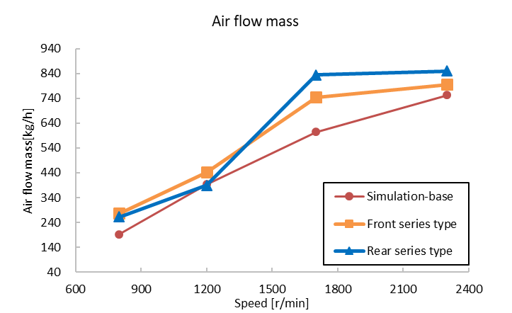
Figure (b). Air flow mass performance between different series types and the base one
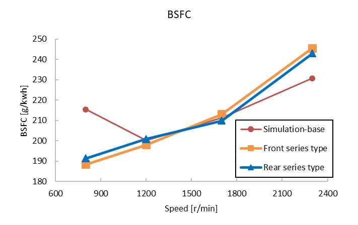
Figure (c). BSFC performance between different series types and the base one
Figure 9. Performance of the series E-Boosting system.
In the series front arrangement, as shown in Figure 10, compare the intake state under the two conditions of opening and closing the bypass valve. When the bypass valve is opened in the series front arrangement, the compressor is located at the back end of the electrical boost and bypass pipelines and has the effect of pumping air, and the part of the electrical boost flow is insufficient by the bypass pipeline; When the bypass valve is closed, the bypass pipeline cannot play the role of air replenisher, the electrical boost flow range is insufficient, and the intake volume required by the supercharger cannot be reached, which will lead to insufficient gas volume and insufficient power in medium and high-speed conditions above 1200 r/min as shown in Figure 11.
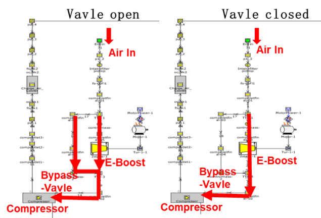
Figure 10. Comparison of series E-Boosting system.
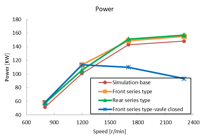
Figure (a). Power performance between different series types
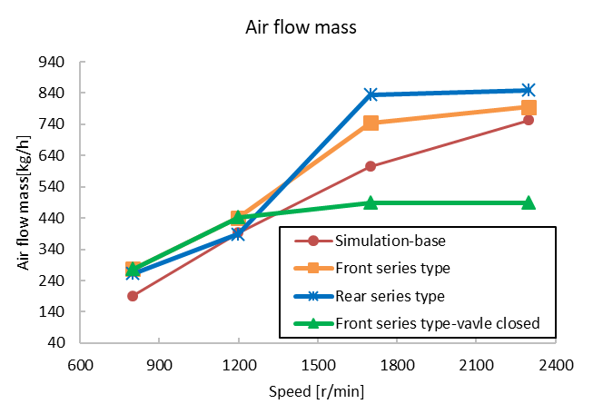
Figure (b). Power performance between different series types
Figure 11. Performance of By-pass valve closed.
Therefore, in the condition of 1200 r/min, it is necessary to open the bypass valve and turn off the motor to make the electrical boost not work, so that the medium-high speed is consistent with the original machine state.
In the rear series system, compare the performance of the two states of the bypass valve. When the bypass valve is closed, because the pressure after electrical boost is greater than the pressure before electrical boost, there is no intake flow in the bypass pipeline, and only when electrical boost is not working, the intake air flows into the engine intercooler from the bypass pipeline, which is equivalent to the base engine with only the turbocharger working separately.
6. Study of Hybrid Conditions
Considering that if the motor power consumption of the electrical boost comes from the engine, the BSFC will deteriorate, so the application of the electrical boost in the hybrid vehicle platform can make full use of the electric energy. Therefore, the performance impact of the electrical boosting system under the transportation condition based on the hybrid engine is studied [17,18]. Therefore, the commonly used driving conditions of the medium-engine hybrid vehicle were selected for research, as shown in Figure 12.
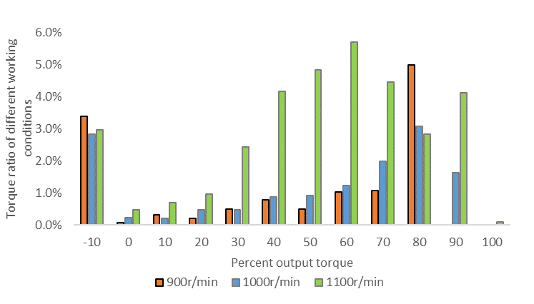
Figure 12. Torque ratio under different hybrid conditions.
The data of 3 typical working conditions with relatively large torque were selected to recalibrate the model, and then a series arrangement (including series front and series back) was selected for simulation analysis. The results are shown in Figure 13.
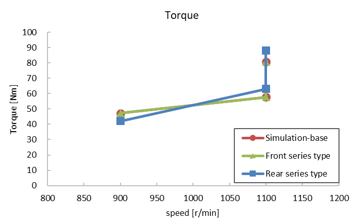
Figure (a). Torque comparison between series types and base under hybrid conditions
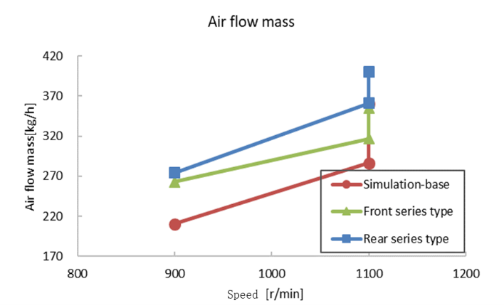
Figure (b). Air flow mass comparison between series types and base under hybrid conditions
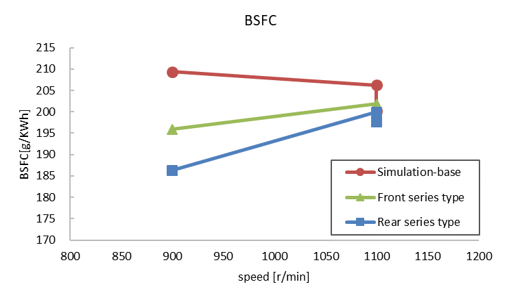
Figure (c). BSFC comparison between series types and base under hybrid conditions
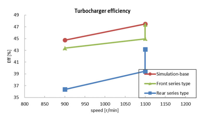
Figure (d). Turbocharger efficiency comparison between series types and base under hybrid conditions
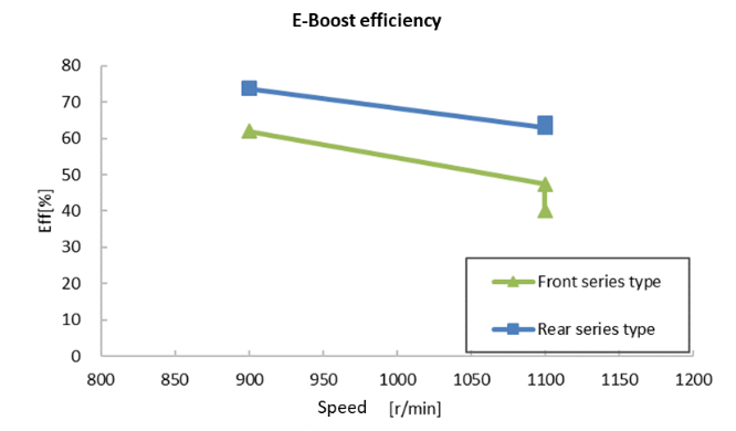
Figure (e). E-Boost efficiency comparison between series types and base under hybrid conditions
Figure 13. Simulation results of the electrical boosting system under hybrid conditions.
It can be seen from Figure 13 that both power and torque can reach the original engine level when the two series arrangement forms are adopted. Regardless of motor power consumption, the rear is better than the front, and the fuel consumption is optimized by up to 11%. The three working conditions are partial load, there is no supercharger overspeed problem, and there is no maximum combustion pressure overlimit problem. The electric compressor is more efficient in the rear series system, and the turbocharger is more efficient in the front series system.
7. Conclusions
The electrification of the diesel engine is an important technical way to save energy and reduce emissions. Compared with the turbocharging system of the traditional diesel engine, the electrical boosting system can further improve the charging efficiency of the diesel engine, and improve the low-speed torque and transient response. The conclusions of this paper are as follows:
(1) Based on a mass-produced medium-sized diesel engine platform and the corresponding hybrid platform, the influence of the electrical boosting system on power performance and fuel economy under the parallel layout, series-front layout, and series-rear layout of the electrical boosting system was studied. The results show that the parallel electrical boosting system can increase the low-speed torque by up to 9%, improve the intake air volume by 42%, and reduce the specific fuel consumption by 9%. However, when using the parallel layout, an electrical boost similar in size to the turbocharger needs to be used in combination and re-matched to achieve the best results.
(2) When arranged in series at the front, the low-speed torque can be increased by 13%, the intake air volume can be increased by 44%, and the BSFC (brake specific fuel consumption) can be improved by 12%. When arranged in series at the rear, the torque can be increased by 11%, the intake air volume can be increased by 37%, and the BSFC can be improved by 11%. However, an additional intercooler is required for the rear layout, which increases the cost. Moreover, the electric compressor only operates under low-speed conditions to increase torque and optimize fuel consumption. At high speeds, further optimization of the matching with the original engine turbocharger is needed.
(3) Under the typical hybrid operating conditions of the hybrid platform, both power and torque can reach the target levels. The rear layout is superior to the front layout. The specific fuel consumption can be optimized by up to 11%. The rear electrical boost has a higher efficiency, while the front turbocharger has a higher efficiency. There is still room for optimization in the existing matching schemes of the electric boosting system.
(4) For diesel engines, the larger the displacement, the larger the electrical boost required for matching, and the higher the requirements for the rotational speed, power, and reliability of the corresponding motor. Therefore, there are currently no mass-produced electrical boost for large-displacement diesel engines on the market. Thus, the electrical boosting system for medium-sized engines described in this paper has a more promising commercialization prospect.
Author Contributions: Y.Y.: conceptualization, methodology; J.M., Y.Z., Z.L.: data curation, writing—original draft preparation; Y.Y., J.M.: writing—reviewing and editing. All authors have read and agreed to the published version of the manuscript.
Funding: This research received no external funding.
Institutional Review Board Statement: Not applicable.
Informed Consent Statement: Not applicable.
Data Availability Statement: Not applicable.
Conflicts of Interest: The authors declare that they have no known competing financial interests or personal relationships that could have appeared to influence the work reported in this paper.
Abbreviations
|
E-Boost |
Electrical boost |
|
BSFC |
Brake specific fuel consumption |
|
FGT |
Fixed gate turbocharger |
|
WGT |
Waste gate turbocharger |
|
VGT |
Variable geometry turbocharger |
|
PM |
particulate matter |
|
NOx |
Nitric oxides |
|
NVH |
Noise Vibration Harshness |
|
AFR |
Air-fuel ratio |
|
EGR |
Exhaust gas recirculation |
References
- Chu, S.; Majumdar, A. Opportunities and challenges for a sustainable energy future. Nature 2012, 488, 94–303.
- Zhou, L. Internal Combustion Engine, 3rd ed.; China Machine Press: Beijing, China, 2010; pp. 65–67.
- Uchinda, H. Trend of turbocharger technologies. Res. Dev. Rev. Toyota Cent. Res. Dev. Labs 2006, 41, 1–8.
- Yamashita, Y.; Iba Raki, S.; Ogita, H. Development of Electrically Assisted Turbocharger for Diesel Engine. In 8th International Conference on Turbochargers and Turbocharging; Woodhead Publishing: Sawston, UK, 2006; pp. 147–155.
- An, B.; Shibata, N.; Suzuki, H.; Ebisu, M. Development of two-stage turbocharger system with electric super-charger. In Proceedings of the FISITA 2012 World Automotive Congress, Beijing, China, 27–30 Novemeber 2013; pp. 147–155.
- Rode, M.; Suzuki, T.; Iosifidis, G.; Scheuermann, T. Electric turbocharger concept for highly efficient internal combustion engines. MTZ Worldw. 2019, 80, 120–125.
- Romagnoli, A.; Vorraro, G.; Rajoo, S.; Copeland, C.; Martinez-Botas, R. Characterization of supercharger as boosting & turbo-expansion device in sequential multi-stage systems. Energy Convers. Manag. 2017, 136, 127–141.
- Murgovski, N.; Marinkov, S.; Hilgersom, D.; de Jager, B.; Steinbuch, M.; Sjöberg, J. Powertrain sizing of electrically supercharged internal combustion engine vehicles. ScienceDirect 2015, 48, 101–108.
- Trvcar, G.; Bizjan, F.; Katrasnik, T. Methods for improving transient response of diesel engines influences of different electrically assisted turbocharging topologies. J. Automob. Eng. 2011, 225, 1167–1185.
- Baek, S.; Lee, H.; Lee, K. Fuel efficiency and exhaust characteristics of turbocharged diesel engine equipped with an electric supercharger. Energy 2021, 214, 119049.
- Mamat, A.B.; Martinez-Botas, R.F.; Rajoo, S.; Romagnoli, A.; Petrovic, S. Waste heat recovery using a novel high performance low pressure turbine for electric turbo-compounding in downsized gasoline engines. Energy 2015, 90, 218–234.
- Breitbach, H.; Christmann, R.; Gabriel, H.; Metz, D. The second generation eBooster from BorgWarner. MTZ Worldw. 2020, 81, 42–45.
- Aghaali, H.; Ångström, H.E. A review of turbocompounding as a waste heat recovery system for internal combustion engines. Renew. Sustain. Energy Rev. 2015, 49, 813–824.
- Leng, L.; Ma, Z.; Cheng, J.; Shi, L.; Deng, K. Research on exhaust energy distribution regulation for fuel economy improvement of turbocompound diesel engine. Appl. Therm. Eng. 2023, 220, 119708.
- Zhao, R.; Huang, L.; Wang, Z.; Zhuge, W.; Ding, Z.; Zhang, Y. Development of a novel dual-loop optimization method for the engine electric turbocompound system based on particle swarm algorithm. Energy 2023, 284, 129310.
- Liu, R.J.; Guan, J.F.; Liu, G. Status of application technology of electric supercharger. Small Intern. Combust. Engine Motorcycle 2009, 38, 41–43.
- Oh, H.; Lee, J.; Woo, S.; Park, H. Effect of synergistic engine technologies for 48V mild hybrid electric vehicles. Energy Convers. Manag. 2021, 244, 114515.
- Baek, S.; Woo, S.; Kim, Y.; Lee, K. Prediction of turbocharged diesel engine performance equipped with an electric supercharger using 1D simulation. Energy 2021, 185, 213–228.
- Yao, C.; Han, W.; Xu, G.; Li, F.; Hou, Y.; Wu, Y. Research and experimental studies on the influence on turbocharger by electric supercharger. J. Mech. Eng. 2012, 48, 188–193.
- Okui, N. A study on improvement of fuel economy of heavy duty hybrid trucks with new type of hybrid electric assist engine System. SAE Int. 2016, 9, 41–50. https://doi.org/10.4271/2016-01- 2358.
- Grönman, A.; Sallinen, P.; Honkatukia, J.; Backman, J.; Uusitalo, A. Design and experiments of two-stage intercooled electrically assisted turbocharger. Energy Convers. Manag. 2016, 111, 115–124.
- Keidel, S.; Wetzel, P.; Biller, B.; Bevan, K.; Birckett, A. Diesel engine fuel economy improvement enabled by supercharging and downspeeding. SAE Int. J. Commer. Veh. 2012, 5, 483–493. https://doi.org/10.4271/2012-01-1941.


